

Passive Liquid Cooling Jacket
Abstract
Abstract
INTRODUCTION
Electric Vehicles (EVs) are rapidly gaining popularity due to their environmental benefits and high energy efficiency. However, one of the major challenges in EV systems is excessive heat generation in electric motors, particularly in BLDC (Brushless DC) motors. During operation, these motors experience high current loads, continuous rotation, and both electrical and mechanical losses - all of which contribute to significant thermal stress.
Unmanaged heat generation leads to reduced motor efficiency, damage to winding insulation and internal components, and a shortened operational lifespan of the motor. To address these concerns, effective thermal management systems are essential. Among available solutions, liquid cooling stands out for its high heat absorption capacity, where a circulating coolant absorbs heat from the motor surface and carries it away, maintaining optimal operating temperature.
This project proposes a passive liquid cooling jacket - a device that surrounds the motor body and channels coolant flow around it without relying on active thermal feedback control. The jacket is designed to be retrofittable, requiring no structural modification to the motor itself, making it a practical solution for both new and existing EV applications.
TECHNOLOGIES USED
SolidWorks (CAD Design)
ANSYS Fluent (CFD Simulation)
3D Printing (Fabrication)
ESP32 Microcontroller (Sensor Data Acquisition)
Thermocouples and Flow Sensor (Experimental Measurement)
LITERATURE SURVEY
“Efficiency Evaluation on Cooling Behavior of Water-Cooling Jacket for Synchronous Reluctance Motor" (Nguyen et al., 2024)
This study investigated the effectiveness of a water-cooling jacket applied to a synchronous reluctance motor. Key findings showed a significant reduction in stator winding temperature by approximately 19°C and outer surface temperature by approximately 16°C following jacket implementation. Cooling performance was found to improve with increasing coolant flow rate up to an optimal value of approximately 20 L/min, beyond which marginal gains became negligible. The study also established that a longer, well-designed coolant path increases the heat transfer coefficient, resulting in better heat dissipation. Notably, external cooling jackets can be added without modifying the motor structure, confirming their suitability for retrofit applications in EVs.
"Analysis of Cooling Characteristics of Permanent Magnet Synchronous Motor with Different Water Jacket Design" (Jeon et al., 2023)
Jeon et al. analysed the influence of various water jacket design parameters on cooling performance for a permanent magnet synchronous motor. The study established that cooling efficiency depends on mass flow rate, number of cooling passes, and inlet-outlet configuration. A 6-pass cooling jacket configuration was identified as providing the best balance between temperature reduction and pressure drop, with additional passes beyond this yielding minimal benefit at the cost of increased flow resistance. Increasing flow rate reduces temperature up to a threshold of approximately 0.025 kg/s, after which pressure drop increases significantly without proportional cooling improvement. A design featuring one inlet and two outlets was found to provide efficient cooling with minimal pressure loss.
These two studies collectively guided the channel geometry and flow path design decisions adopted in the present project.
METHODOLOGY
The project was executed through six sequential steps: design, simulation, fabrication, system assembly, testing, and analysis and validation.
Step 1: Design
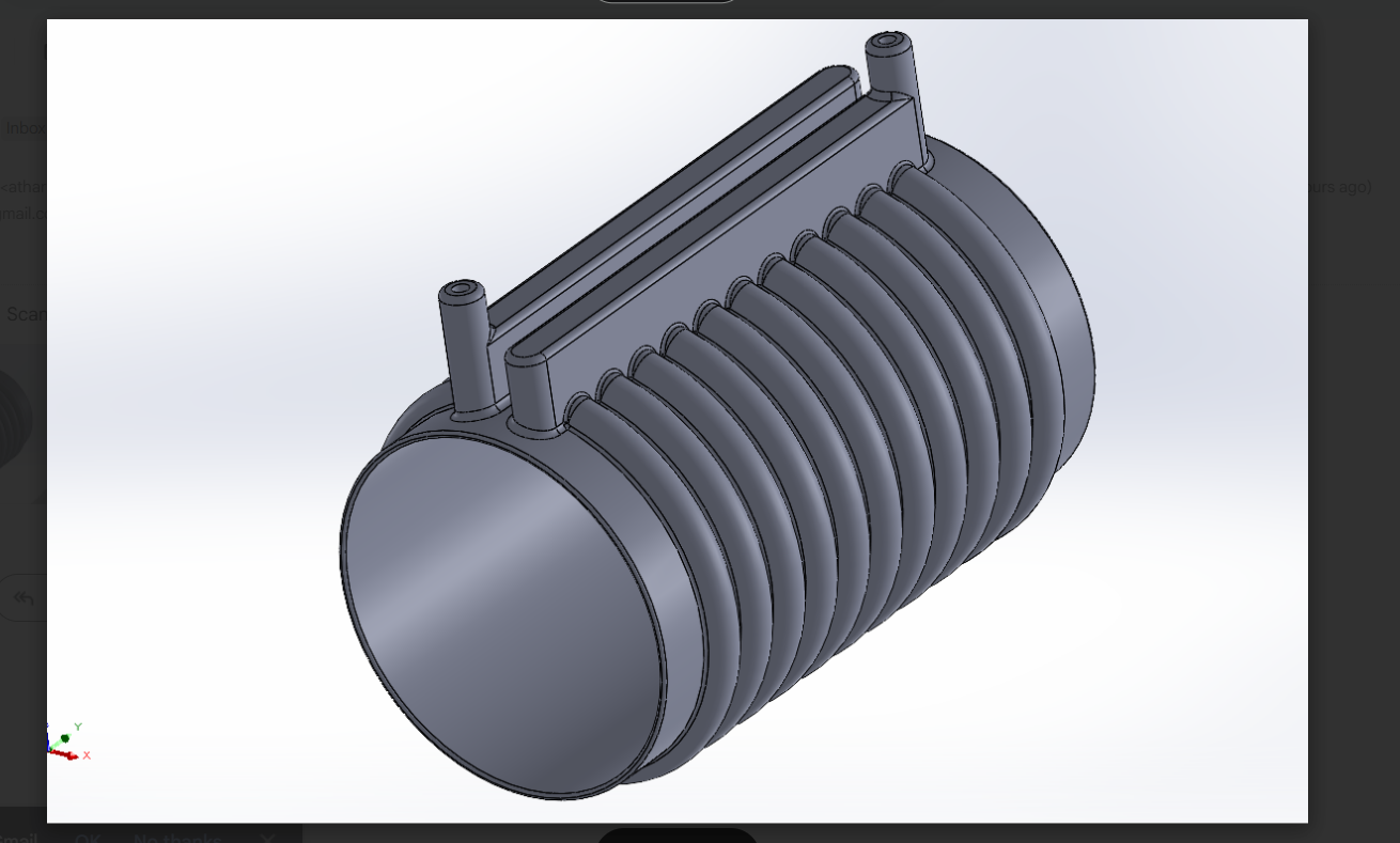
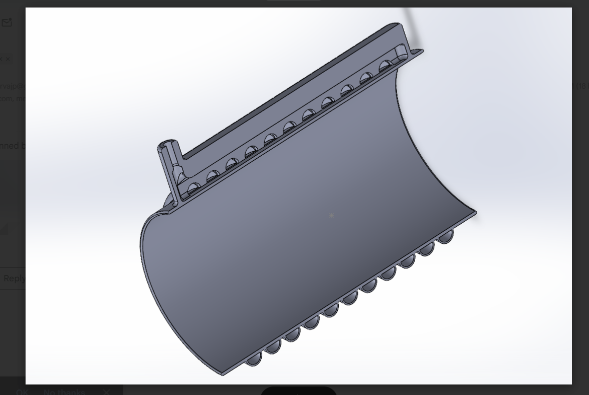
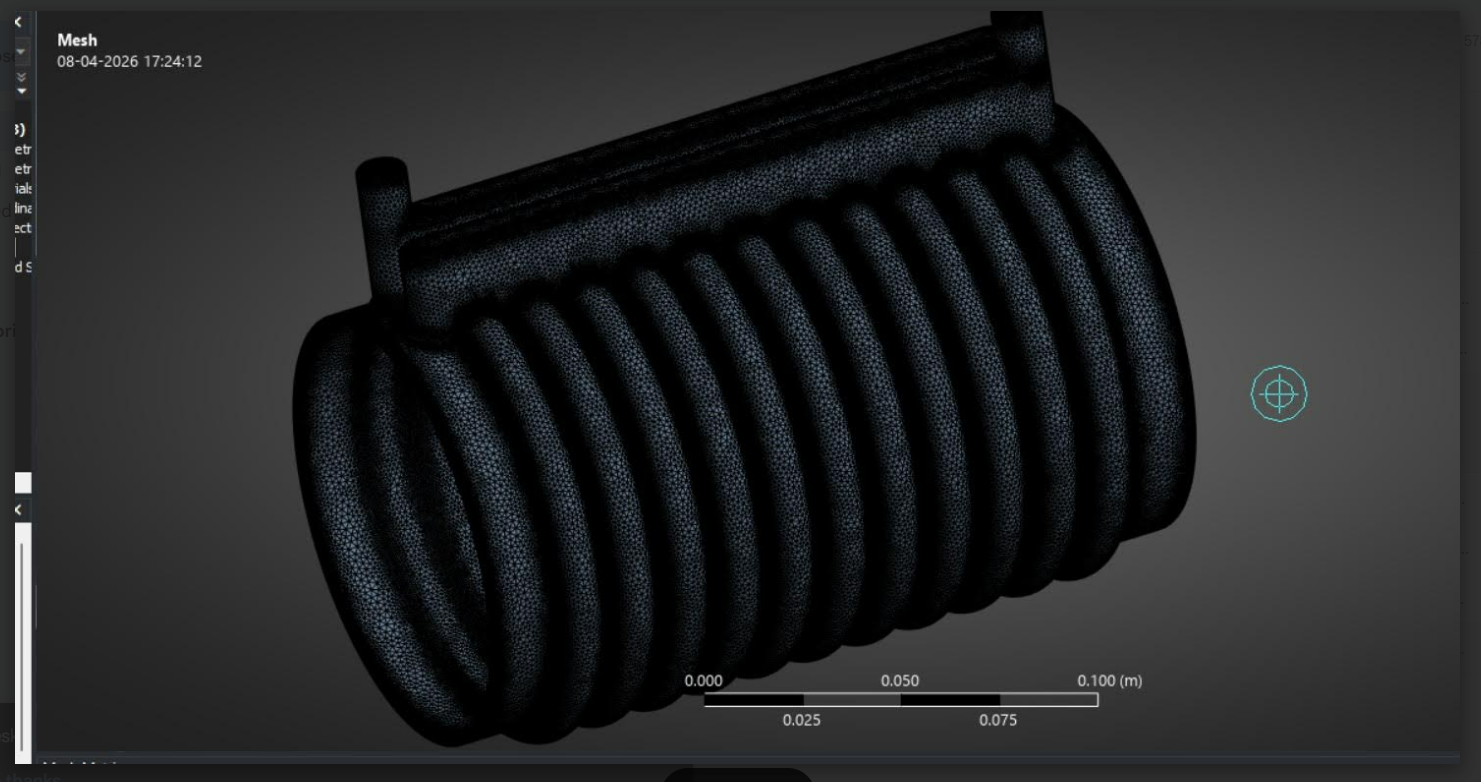
The cooling jacket was modelled using SolidWorks CAD software. The channel geometry was optimised to maximise the heat transfer surface area while maintaining structural integrity for 3D-printed fabrication. The design incorporates a helical coolant channel wrapped around the cylindrical motor body, with inlet and outlet ports positioned for efficient flow distribution. Two design configurations were produced - a full outer jacket view and a cross-sectional half-jacket - to verify channel depth and wall thickness.
Step 2: Simulation
Thermal and fluid analysis was performed using ANSYS Fluent (Version 2026 R1). CFD simulations studied temperature distribution across the jacket surface and coolant flow behaviour within the channels. Two simulation conditions were evaluated:
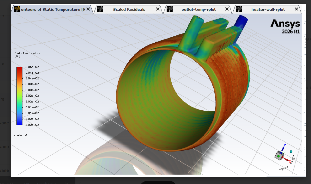
1. Static temperature contour analysis - visualising heat distribution across the cooling jacket exterior under a defined heat flux applied at the inner wall (representing the motor surface).
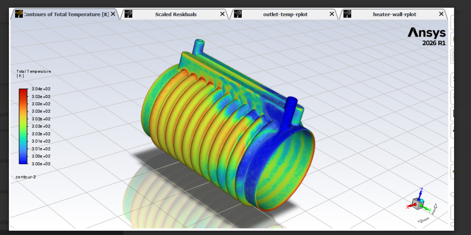
2. Total temperature contour analysis - mapping coolant temperature rise from inlet to outlet to assess heat absorption effectiveness.
The CFD results established the expected temperature differentials between jacket inlet and outlet, providing a benchmark for experimental validation.
Step 3: Fabrication
The cooling jacket prototype was manufactured using FDM (Fused Deposition Modelling) 3D printing. This method was selected for its ability to reproduce complex helical channel geometries with reasonable dimensional accuracy and low cost, making it suitable for prototype-level validation.
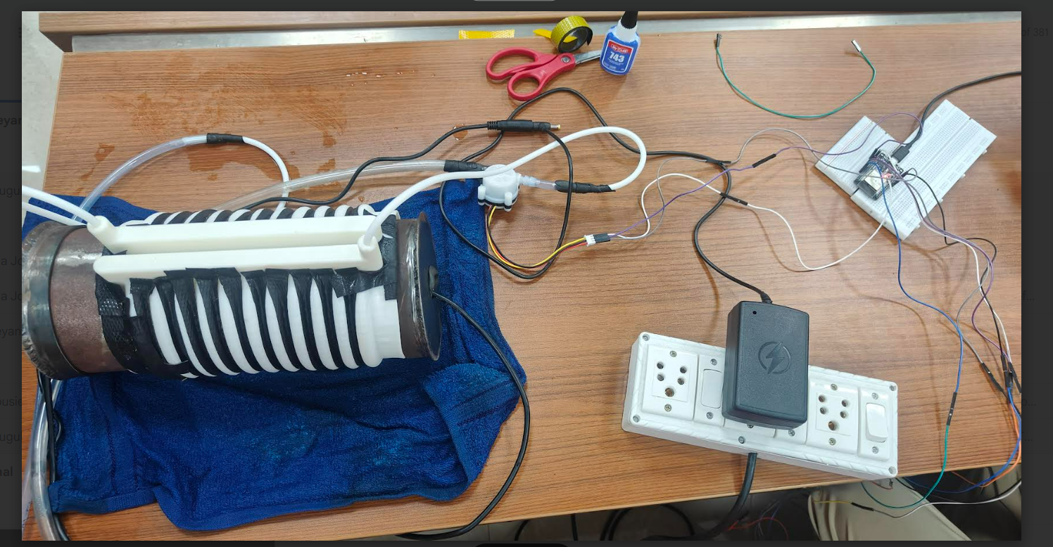
Step 4: System Setup
The experimental test rig was assembled with the following components:
1. 3-D printed water cooling jacket
2.Thermocouple sensor
3. Flow sensor
4.Heating rod
5.ESP32
6.Bread Board
7.Fuse
8.Metal cylinder
9.M-seal
10.Pump
11.Jumper Wires
Step 5: Testing
The heating element was powered under defined load conditions. Inlet and outlet temperature data were continuously recorded using thermocouples interfaced with the ESP32. The flow sensor at the inlet logged coolant flow rate simultaneously. Multiple test runs were conducted at varying power inputs to assess cooling performance across different heat generation levels.
Step 6: Analysis and Validation
Experimental temperature readings were compared against CFD simulation results. Cooling performance metrics - including temperature differential across the jacket (ΔT) and heat removal rate - were evaluated. The comparison between experimental and simulation data was used to validate the fidelity of the CFD model and assess the real-world effectiveness of the cooling jacket design.
WORKING PRINCIPLE
The system operates on the principle of forced convective heat transfer between a heat-generating metal cylinder (simulating a motor body) and a flowing coolant.
Heat Generation: When electrical power is supplied to the heating rod, heat is generated and transferred to the surrounding sheet metal cylinder via conduction and natural convection. The cylinder surface temperature rises in a manner analogous to the stator housing of an operating BLDC motor.
Cooling Mechanism: The 3D-printed cooling jacket surrounds the metal cylinder and forms sealed coolant channels around its outer surface. A pump drives coolant - water - through the jacket continuously. Heat is transferred from the hot cylinder surface to the cooler flowing coolant by convection.
Coolant Circulation: Coolant enters the jacket through the inlet port equipped with a flow sensor that measures volumetric flow rate. As the coolant travels through the helical channel, it progressively absorbs thermal energy from the cylinder wall. The heated coolant exits through the outlet port, where a thermocouple records its exit temperature.
Measurement and Monitoring
The ESP32 microcontroller is used to acquire data from both the flow sensor and temperature sensors in real time, enabling continuous monitoring and logging of inlet flow rate and coolant temperatures. The temperature sensors measure the inlet and outlet temperatures of the coolant, while the flow sensor provides the flow rate of the fluid circulating through the cooling jacket.
This data is utilized to calculate the rate of heat removal from the system using the relation:
Q˙=m˙⋅cp⋅ΔT
where m˙ is the mass flow rate of the coolant, cp is the specific heat capacity of water (4186 J/kg·K), and ΔT is the temperature difference between the outlet and inlet of the coolant. This calculation provides a quantitative measure of the cooling performance of the system under different operating conditions.
System Behaviour: Continuous coolant circulation maintains temperature control by preventing heat accumulation on the cylinder surface. Consistent with published literature, higher flow rates improve heat removal capacity up to a saturation point, beyond which pressure drop penalties reduce the net benefit.
RESULT
The CFD simulation in ANSYS Fluent demonstrated clear temperature gradients across the cooling jacket geometry. The static temperature contour plot showed the lowest temperatures near the inlet side of the jacket, where fresh coolant enters, with a progressive increase toward the outlet as the coolant absorbs heat from the simulated motor surface. The higher heat transfer rate near the inlet is attributed to the larger temperature difference between the coolant and the heated surface. The total temperature contour across the full assembly confirmed effective heat extraction, with the coolant exiting at a measurably higher temperature than at entry.
Experimental results from the test rig are expected to corroborate the trend established by simulation, with the ESP32-logged ΔT values between inlet and outlet thermocouples providing direct quantitative evidence of cooling effectiveness under each load condition. Any deviations between experimental and CFD results can be attributed to thermal contact resistance at the jacket-cylinder interface, heat losses to the surroundings, and minor flow non-uniformities in the 3D-printed channels.
References:
https://www.mdpi.com/2475086
https://ph01.tci-thaijo.org/index.php/jrame/article/view/253967
Report Information
Team Members
Team Members
Report Details
Created: April 8, 2026, 6:54 p.m.
Approved by: Santoshkumar Suresh Otageri [Piston]
Approval date: None
Report Details
Created: April 8, 2026, 6:54 p.m.
Approved by: Santoshkumar Suresh Otageri [Piston]
Approval date: None