

Symmetric FIR filter in Verilog
Abstract
Abstract
GitHub Repository : https://github.com/PDK34/FIR_filter_Verilog
Google Meet Link: http://meet.google.com/ava-pfee-bmt
Aim
The aim of this project is to:
- Design a 12-tap symmetric low-pass FIR filter at the RTL level using Verilog HDL.
- Implement coefficient symmetry to halve the number of multiplications from 12 to 6.
- Apply a 3-stage pipeline architecture to achieve one-sample-per-clock throughput.
- Verify the design through RTL simulation and compare the output against a Python-generated reference model.
- Gain hands-on experience in fixed-point arithmetic, pipelining, and RTL verification methodologies.
Introduction
Digital filters are fundamental building blocks in signal processing systems, used in applications ranging from audio processing to communications and biomedical engineering. Among them, FIR (Finite Impulse Response) filters are widely preferred for their inherent stability, guaranteed linear phase response, and ease of design.
A standard FIR filter computes the output y[n] as a weighted sum of the current and past N input samples:
y[n] = h[0]x[n] + h[1]x[n-1] + h[2]x[n-2] + … + h[N-1]x[n-N+1]
For a 12-tap filter, this requires 12 multiplications per output sample. However, symmetric FIR filters (where h[k] = h[N-1-k]) allow us to exploit this symmetry by pre-adding symmetric input pairs before multiplication, reducing the number of multipliers from 12 to 6 , which is a significant hardware saving.
This project implements such a symmetric FIR filter at the RTL level using Verilog, with a three-stage pipelined datapath to maximise throughput. The complete design is structured as four interconnected modules: a serial coefficient loader, a tapped delay line, a pre-adder, and a pipelined multiply-accumulate unit.
Literature Survey and Technologies Used
FIR Filter Theory
FIR filters are characterised by a finite-length impulse response. The filter output is given by the convolution of the input signal with the filter's impulse response (the coefficient set). Unlike IIR filters, FIR filters have no feedback path, ensuring unconditional stability and making them amenable to hardware implementation.
Symmetric Coefficient Exploitation
A linear-phase FIR filter has symmetric coefficients: h[k] = h[N-1-k]. This means that instead of computing h[k]*x[n-k] and h[N-1-k]*x[n-N+1+k] separately, we can first compute (x[n-k] + x[n-N+1+k]) and multiply by h[k] once. For a 12-tap filter, this reduces 12 multiplications to 6, saving nearly half the hardware resources.
Pipelining in Digital Circuits
Pipelining is a technique where the computation is broken into stages separated by registers. Each stage processes a different sample simultaneously, so while stage 1 processes sample N, stage 2 processes sample N-1, and stage 3 processes sample N-2 simultaneously. This allows one new output to be produced every clock cycle (throughput = 1 sample/cycle), at the cost of a fixed pipeline latency.
Fixed-Point Arithmetic
Hardware does not natively support floating-point. Samples and coefficients are represented as fixed-width integers (fixed-point). The bit widths must be carefully chosen to avoid overflow at each pipeline stage: adding two N-bit numbers requires N+1 bits, and multiplying an M-bit number by a K-bit number requires M+K bits for the full-precision result.
Tools Used
- Verilog HDL - RTL design language
- Xilinx Vivado 2025.2 - simulation and synthesis
- Python (NumPy, Matplotlib, SciPy) - signal generation and reference model
Methodology
Overall Architecture
The complete FIR filter is implemented as a top-level module (symmetricFIR) that instantiates four sub-modules connected in a pipeline chain. The block diagram shows the flow from coefficient loading through sample delay, pre-addition, and finally the pipelined multiply-accumulate stage.
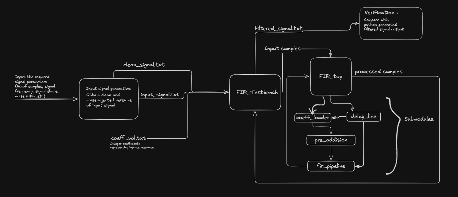
Module 1: Coefficient Loader (coeff_loader)
The coefficient loader is a serial-load interface that accepts filter coefficients one at a time via a load pulse. It maintains an internal index register (idx) that tracks which slot to write into. On each rising clock edge when load is high and loading is not yet complete, the incoming coefficient value is written into the corresponding slot of the flat output bus coeff_bus. After all 6 coefficients are loaded, the coeff_valid output is asserted, signalling downstream modules that they can begin processing. An asynchronous clear (clr) resets the entire state immediately.
Key parameters:
COEFF_NUM = 6 (one coefficient per symmetric pair)
COEFF_WIDTH = 8 (8-bit signed coefficients)
Module 2: Tapped Delay Line (delay_line)
The delay line implements a 12-register shift chain. On each rising clock edge when enabled, the new input sample shifts into the first register (tap[0]) and all existing values cascade one position toward tap[11]. All 12 tap values are simultaneously accessible every clock cycle via a flat output bus (taps_bus), where tap[i] occupies bits [(i+1)*DATA_WIDTH-1 : i*DATA_WIDTH].
A fill counter tracks how many samples have been shifted in, asserting line_full only after all 12 positions contain real data. This prevents meaningless output during the initial fill period. The enable input (en) is connected to coeff_valid from the coefficient loader, so samples only enter the delay line after all coefficients are loaded.
DATA_WIDTH = 12 (12-bit signed samples)
DATA_DELAY = 12 (12 taps)
Module 3: Pre-Adder (pre_adder)
This module implements the first stage of the pipeline. The pre-adder exploits the symmetric coefficient property. For each of the 6 symmetric pairs, it adds the corresponding taps:
Stage 1 — pre-addition: presum[j] = tap[j] + tap[11-j] for j = 0, 1, 2, 3, 4, 5
The results are stored in a flat output bus (presums_bus). Each presum is 13 bits wide (DATA_WIDTH + 1) to accommodate the potential carry from adding two 12-bit numbers. A valid_out signal is generated as a one-cycle delayed version of the enable input, since the addition is registered and takes one clock cycle.
Module 4: FIR Pipeline (fir_pipeline)
This module implements the other two stages of the pipeline:
Stage 2 — Multiply: Each of the 6 presums is multiplied by its corresponding coefficient (mul_reg[j] = presum[j] × coeff[j]). Results are registered into mul_reg, a 6-element array of 22-bit signed registers.
Stage 3 — Accumulate: All 6 products are summed to produce the final filter output (data_out = Σ mul_reg[j]).
Bit widths are carefully tracked to prevent overflow: STAGE2_WIDTH = 22 bits (13+8+1), STAGE3_WIDTH = 26 bits (22 + ⌈log₂(6)⌉ + 1). The valid signal is pipelined through both stages, so valid_out goes high exactly when data_out contains a valid filtered sample.
Pipeline Timing
The complete pipeline introduces a latency of 3 clock cycles from when data enters the delay line to when the first valid output appears. After this initial latency, one new filtered sample is produced every clock cycle, giving a throughput of 1 sample/cycle:
delay_line (cycle N) → pre_adder (cycle N+1) → multiply (cycle N+2) → accumulate/output (cycle N+3)
Python Reference Model and Verification Flow
A Python script generates the test stimulus and reference output. It produces a noisy version of the chosen signal (square wave at 10Hz, 2000 samples, noise amplitude 0.2), quantises it to 12-bit fixed-point, applies the same 12-tap FIR filter using NumPy convolution, and saves the input and coefficient files as text files for the Vivado testbench to read.
The Vivado testbench (symmetricFIR_tb) reads these files, feeds samples into the RTL design clock by clock, and writes the filtered output to filtered_signal.txt. The Python script then reads this file and overlays the RTL output against the Python reference to verify correctness.
Results
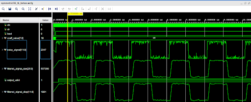
Vivado Simulation Waveform
The Vivado RTL simulation confirms the correct operation of the full pipeline. The waveform shows the noisy input signal entering the delay line after coefficients are loaded (coeff_valid goes high), the output valid signal asserting after the pipeline fills, and the filtered output clearly smoother than the noisy input.
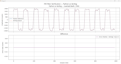
Python vs Verilog Comparison
The filtered output from the Vivado simulation was extracted and compared against the Python reference model. The two outputs overlay almost exactly across all 2000 samples, confirming that the RTL implementation is functionally correct.
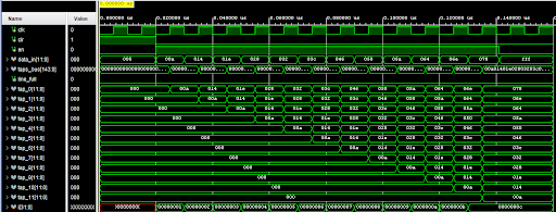
Delay Line Verification
The delay line module passed all 5 automated testbench checks: asynchronous reset clears all taps immediately, line_full stays low for the first 11 samples, line_full asserts exactly on the 12th sample, tap values are correctly ordered (newest at tap_0, oldest at tap_11), and no shifting occurs when enable is low.
Error Analysis
Originally there is some error in the waveform visible at the end, which is removed by the python script itself.
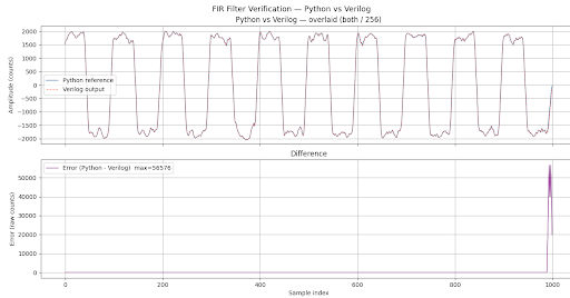
Python's convolution produces a longer output than Verilog does.When Python runs np.convolve(signal, h, mode='full'), it zero-pads the signal at both ends and produces an output of length N + L - 1, where N = number of input samples (2000) and L = filter length (12). That gives 2011 output samples.Verilog, however, only outputs samples while real input data is being streamed. Once the last input sample enters the delay line, the Verilog simulation ends, it never zero-pads. So Verilog produces exactly 2000 valid outputs.
The final 11 samples in Python's output (mode='full' tail) are computed from a mix of real input data and implicit zeros that don't exist in the Verilog simulation. These are the boundary samples, they correspond to the filter "draining" after the last real input, which Verilog never does. This creates the spike visible at the end of the error plot in Image 2.
By trimming the last 11 samples from both arrays before comparing, the boundary region is excluded entirely. What remains is only the steady-state portion where both Python and Verilog are computing from identical real data — giving the max=0 error result in Image 1.
Conclusions and Future Scope
Conclusions
This project successfully demonstrates the RTL design and simulation of a 12-tap symmetric pipelined FIR low-pass filter in Verilog. The key achievements are:
- A fully functional 4-module pipelined RTL design verified in Vivado simulation.
- Effective exploitation of coefficient symmetry reducing multiplier count from 12 to 6.
- A 3-stage pipeline achieving one output sample per clock cycle after initial latency.
- Correct fixed-point arithmetic with carefully tracked bit widths at each pipeline stage.
- End-to-end verification with a Python reference model confirming RTL functional correctness.
Future Scope
- FPGA implementation and real-time testing on a physical board (e.g. Basys 3, Nexys A7).
- Extension to higher-order filters (16, 32 taps) for improved noise suppression.
- Integration with a UART control interface for dynamic coefficient updates.
- Resource utilisation comparison between symmetric and non-symmetric FIR implementations.
- Polyphase filter bank implementation for multi-rate signal processing applications.
References
- Proakis, J.G. and Manolakis, D.G., Digital Signal Processing: Principles, Algorithms, and Applications, Prentice Hall.
- Palnitkar, S., Verilog HDL: A Guide to Digital Design and Synthesis, Prentice Hall.
- FIR Filter Implementation in FPGA, Verilog - hackster.io
- Xilinx Vivado Design Suite User Guide, AMD/Xilinx, 2025.
Team
Mentors
- Parthip Dev K K
- Mula Varun Uthej Reddy
- Hardhik Thiriveedi
Mentees
- Harnish Dave
- Shreshtha Kar
- Adithyan P
- Rishabh Mall
- Aditya Chaudhary
Report Information
Report Details
Created: May 12, 2026, 7:34 p.m.
Approved by: Rishadd Ranjith [Diode]
Approval date: None
Report Details
Created: May 12, 2026, 7:34 p.m.
Approved by: Rishadd Ranjith [Diode]
Approval date: None