

Predictive Structural Analysis & Traffic Load Monitoring for Bridge Optimization
Abstract
Abstract
Gmeet link : https://meet.google.com/gpy-fehy-buq
Aim
To develop a contactless bridge monitoring system that utilizes Computer Vision (YOLOv8) and Finite Element Analysis (FEA) to analyze structural integrity, identify potential weak points in design/materials, and implement pre-emptive reinforcements to ensure resource efficiency and long-term durability.
Introduction
Traditional civil engineering workflows evaluate structural reliability using worst-case theoretical models or destructive physical testing, which can lead to over-engineered material waste or unforeseen fatigue failure. This project establishes a real-time smart infrastructure workflow by generating a functional "digital twin" of a bridge.
By leveraging neural networks to monitor environmental parameters (live vehicular traffic) and automatically passing those metrics into multi-physics simulation environments, structural engineers can visually observe localized deformation, map changing safety factors, and execute geometric modifications prior to physical manufacturing.
Literature Survey and Technologies Used
The implementation relies on bridging the gap between deep learning and computational mechanics through the following technologies:
- Computer Vision (YOLOv8): Used for single-stage object detection to categorize passing vehicles into dynamic mass brackets based on pixel coordinate bounding boxes.
- Autodesk Fusion (Simulation & Generative Workspaces): Utilized for structural configuration, geometric optimization, and Finite Element Method (FEM) discretization to compute stress vectors.
- Scientific Computing Stack: Python, OpenCV (for real-time video manipulation matrix handling), and Ultralytics APIs.
Methodology
1. Structural Configuration & Geometry
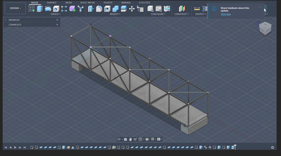
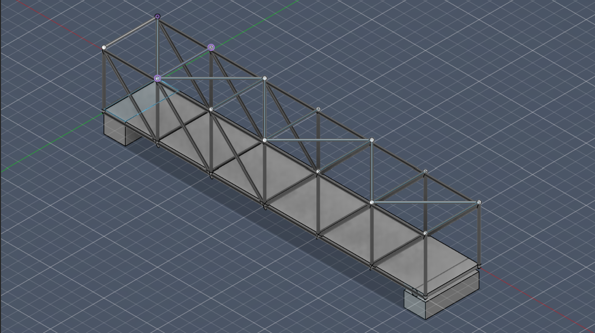
The structural model is designed in a standard Pratt Truss configuration spanning exactly 30 m. The layout consists of hollow square framing tubes welded to a flat solid deck plate, resting on two concrete foundations.
- Structural Steel (Truss Members & Deck Plate): Assigned as the core structural material. Structural Steel was chosen because of its isotropic properties, excellent tensile and compressive resilience (250 MPa Yield Strength), and high Modulus of Elasticity (200 GPa). This allows the members to handle massive, dynamic, high-impact bending moments caused by heavy cargo traffic, flexing slightly under stress and snapping back into shape without undergoing permanent plastic deformation.
- Concrete (Abutment Blocks): Assigned to the foundational support blocks at both ends. Concrete provides massive compressive strength, allowing it to anchor the bridge securely to the ground constraints and absorb the massive downward shear forces transferred from the steel truss joints.
2. Vision System Setup & Load Mapping Engine
The tracking loop scans incoming footage (traffic.mp4). To convert camera pixels into physical spatial meters along our 30 m bridge deck, we defined a region-of-interest boundary (limit_x = int(width * 0.30)). The script identifies a vehicle's bounding box center pixel (center_x), calculates its relative horizontal percentage across the boundary zone, and multiplies it by the total 30 m length:
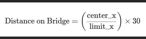
The script tracks exactly where a heavy load is pressing down along the structural span and outputs real-time structural forces using Newton's second law:
F = m . g
Where ‘m’ is the assigned class weight from our dictionary, and g = 9.81 m/s2
3. Python Implementation Script
import cv2
from ultralytics import YOLO
model = YOLO("yolov8n.pt")
vehicle_weights = {
"car": 1500, # ~14.7 kN
"truck": 12000, # ~78.4 kN
"bus": 8000, #~14.7 kN
"motorcycle": 200 # ~14.7 kN
}
cap = cv2.VideoCapture("traffic.mp4 (1).mp4")
frame_count = 0
while cap.isOpened():
ret, frame = cap.read()
if not ret: break
frame_count += 1
if frame_count % 10 != 0: continue # Frame skipping for optimization
height, width, _ = frame.shape
limit_x = int(width * 0.30) # 30% viewport bounds a 30m deck area
results = model(frame)
for r in results:
boxes = r.boxes
for box in boxes:
cls_id = int(box.cls[0])
class_name = model.names[cls_id]
if class_name in vehicle_weights:
x1, y1, x2, y2 = box.xyxy[0]
center_x = int((x1 + x2) / 2)
if center_x <= limit_x:
distance_m = (center_x / limit_x) * 30
mass = vehicle_weights[class_name]
force = mass * 9.81
print(f"Vehicle: {class_name} | Position: {distance_m:.2f} m | Load: {force:.2f} N")
cap.release()
Procedure
1. Computer Vision Feature Extraction
The YOLOv8 nano model (yolov8n.pt), pre-trained on the COCO dataset, was executed inside Google Colab to process the video frame matrix. To optimize frame rates, the script skips every 10 frames (frame_count % 10 != 0). When a vehicle passes through the 30 % threshold line, its class ID is validated against the weight dictionary, and the exact downward force vector is printed to the terminal console log alongside its linear position.
2. Simulation Setup in Autodesk Fusion
The design model was ported directly into the Fusion Static Stress Simulation Workspace.
- Boundary Constraints: To mimic a real-world permanent bridge foundation, Fixed Constraints is applied to one end and Frictionless constraint is applied to the Roller support on the other end .
- Load Application: Instead of applying a generic uniform weight across the bridge, the specific dynamic point forces extracted by our YOLOv8 script were vector-mapped downward (-Fy) onto the target coordinates of the deck plate.
Results
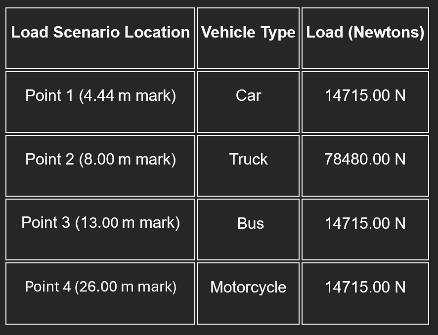
1. YOLOv8 Load Logging Outputs
When running the vision code on our traffic sequence, the model successfully isolated the dynamic forces. To perform a critical stress evaluation, we selected the peak vehicle weights and their exact positions from the running log:
2. FEA Deformation & Stress Results
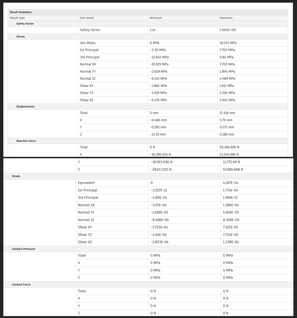
The simulation results indicate the structural response of the bridge under the applied loading conditions. The analysis shows that the stress distribution and displacement values remain within the permissible limits for the selected material. Maximum stress was observed at critical connection and support regions, while the overall deformation of the bridge remained controlled. The safety factor results confirm that the structure is stable and capable of resisting the applied loads safely. The mesh and contact analysis also verified proper interaction between bridge components during loading. Overall, the obtained results demonstrate that the bridge design is structurally efficient, safe, and suitable for the given loading conditions.
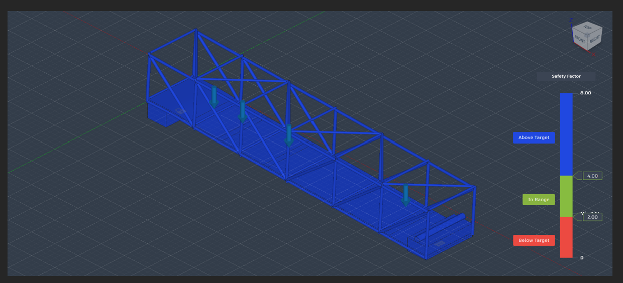
- Finite element analysis of the truss bridge showing applied loads and structural response under simulation. The model indicates a safe design with safety factors remaining within the acceptable range across all members.

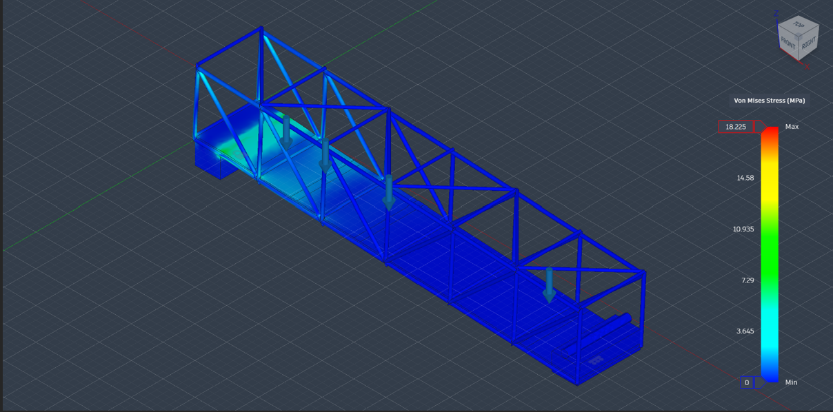
- Von Mises stress distribution analysis of the truss bridge under applied loading conditions. Higher stress concentration is observed near the support region, while the remaining structure stays within safe stress limits.
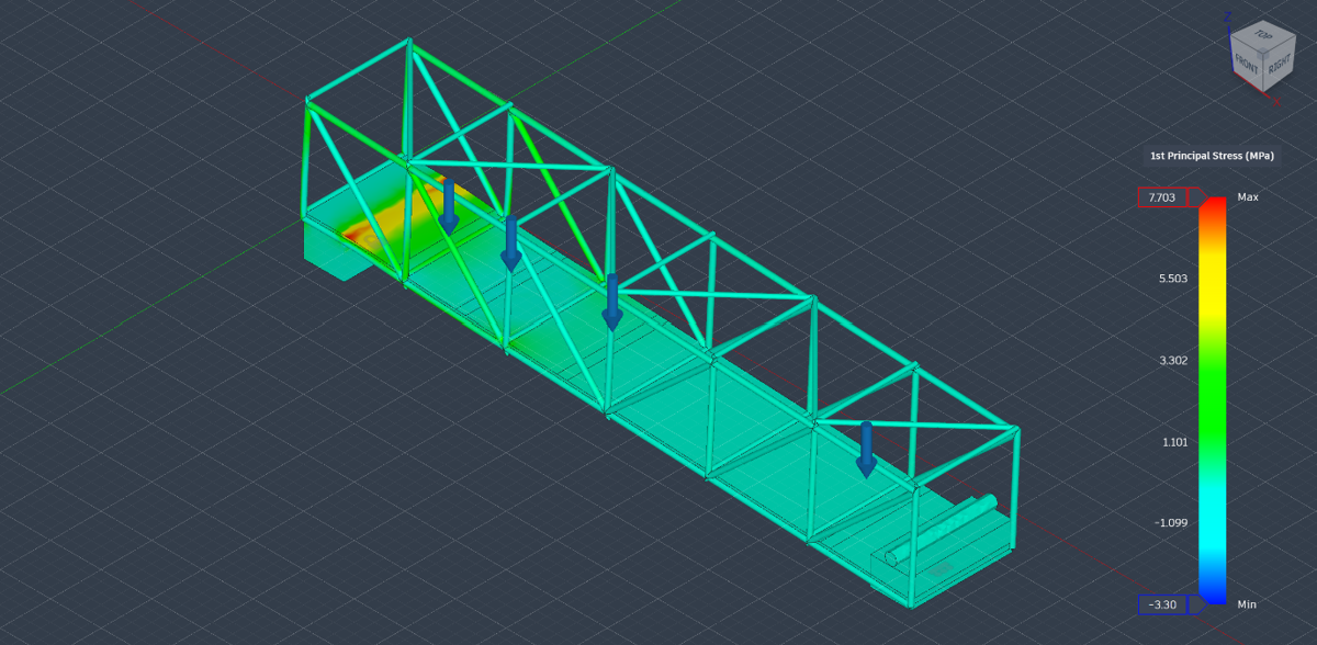
- First principal stress analysis of the truss bridge illustrating stress variation throughout the structure under loading. Maximum principal stress is concentrated near the support section, while the overall bridge maintains stable stress distribution
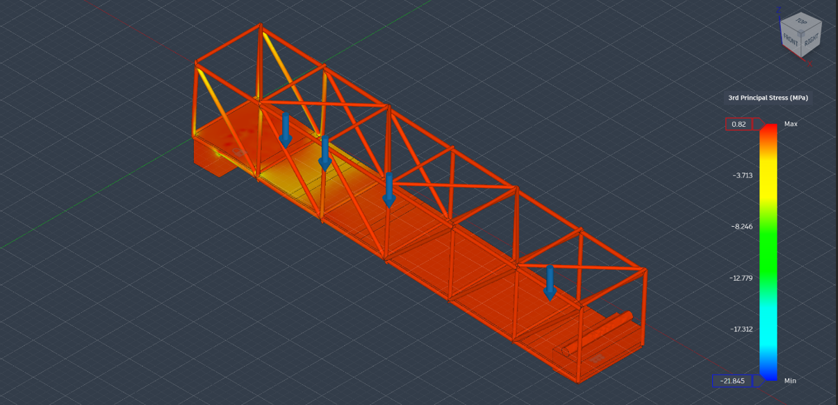
- Third principal stress distribution of the truss bridge under external loading conditions. Compressive stress regions are prominently observed along the deck and support areas, indicating stable structural behavior.
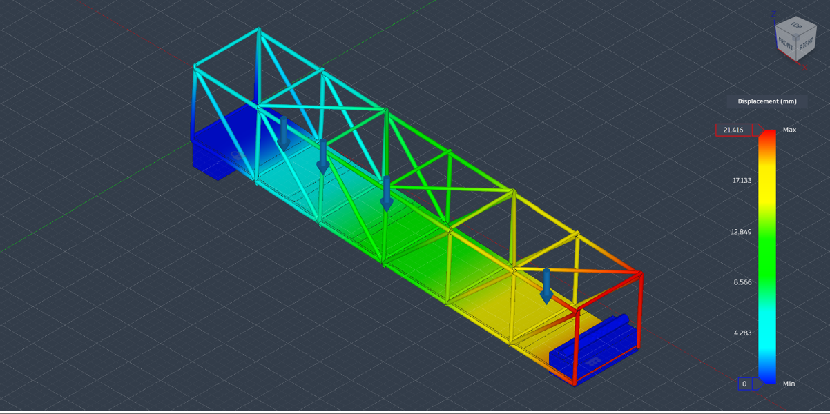
- Structural frame bends under heavy load,Displacement shown in vivid hues. Blue marks stability with minimal shift,Red reveals maximum deformation zones.
Conclusions
This project successfully proves that combining deep-learning computer vision with computational finite element analysis creates a highly effective digital-twin framework for civil infrastructure. Instead of relying on arbitrary "over-building" safety margins that waste raw materials, engineers can use live data to pinpoint exactly where a bridge needs structural support.
Future Scope
- Automated Parametric API Pipelines :To transition from a manual workflow to a true real-time digital twin, the next phase involves developing an automated data loop using a Flask server API. The backend script will capture live YOLOv8 coordinate and load outputs and instantly push them into an active Autodesk Fusion Python script. This will allow the 3D model’s mesh parameters, member thicknesses, and geometry to adjust and update automatically in real time based on live traffic density.
- Dynamic and Transient Mesh Testing :While the current study evaluates worst-case static scenarios, future iterations will shift from Static Stress to a dynamic, time-dependent transient simulation. This upgrade will allow engineers to observe live deflection curves, structural vibrations, and harmonic wave patterns created as a high-tonnage vehicle moves across the physical span of the truss deck.
- Multi-Physics Thermal Expansion Testing :Bridges are subject to intense environmental changes that alter material behavior. Future versions of this digital twin will introduce varying thermal layers within the simulation workspace. This multi-physics approach will analyze how the structural steel expands and contracts under seasonal temperature shifts while simultaneously enduring heavy vehicle load stresses, ensuring complete structural reliability year-round.
References
- Deng, L., et al. (2025). Vision-Based Traffic Load Monitoring in Bridges. ResearchGate.
- Autodesk. (2024). Fusion Simulation: Static Stress Analysis Guide.
- Zhu, J., et al. (2022). Identifying Dynamic Vehicle Loads on Bridges using Computer Vision. IEEE Transactions.
Files:
Google colab nb – https://colab.research.google.com/drive/1H4CyORanMkfNzz7UfNvi9WptLKu3o_ZI
Bridge model -

Mentors & Mentees Details
Mentors:
- Diya
- Joshita
- Sreenidhi
Mentees:
- Navya
Report Information
Report Details
Created: May 15, 2026, 10:51 p.m.
Approved by: None
Approval date: None
Report Details
Created: May 15, 2026, 10:51 p.m.
Approved by: None
Approval date: None