

Path Planning of a Robot using Deep Reinforcement Learning
Abstract
Abstract
INTRODUCTION
Autonomous mobile robots are transforming various industries with their ability to navigate complex environments. Path planning is a critical component of this autonomy, determining an optimal collision-free path from a starting point to a goal. This project investigates the development of a path-planning system for a robot using a novel approach that combines Reinforcement Learning (RL) with Robot Operating System 2 (ROS2) and LiDAR (Light Detection and Ranging) sensor data.
The chosen RL algorithm for this project is TD3 (Twin Delayed Deep Deterministic Policy Gradient). TD3 was selected after careful consideration and comparison with other prominent RL algorithms for path-planning tasks. This selection process considered performance, stability, and data efficiency. One key limitation addressed by TD3 is the overestimation of Q-values, a common issue in previous DDPG algorithms. By employing twin critics and target policy noise injection, TD3 fosters more stable and data-efficient learning. These improvements make TD3 a compelling choice for real-world robot navigation applications.ROS2 facilitates communication between robot components, sensor integration, and code organization. This project leverages ROS2 for efficient communication, allowing the integration of LiDAR data with the RL agent for real-time environment perception. By leveraging LiDAR data for environment awareness, the project strives to develop a robust and adaptable path-planning system capable of navigating diverse environments. The success of this project holds significant potential for advancements in autonomous robot navigation, particularly in applications requiring real-time decision-making in dynamic environments.
METHODOLOGY
This project aimed to develop a robot path planning system using Reinforcement Learning (RL) within the Robot Operating System 2 (ROS2) framework. LiDAR (Light Detection and Ranging) data was used for real-time environment perception.
The methodology can be divided into three main stages:
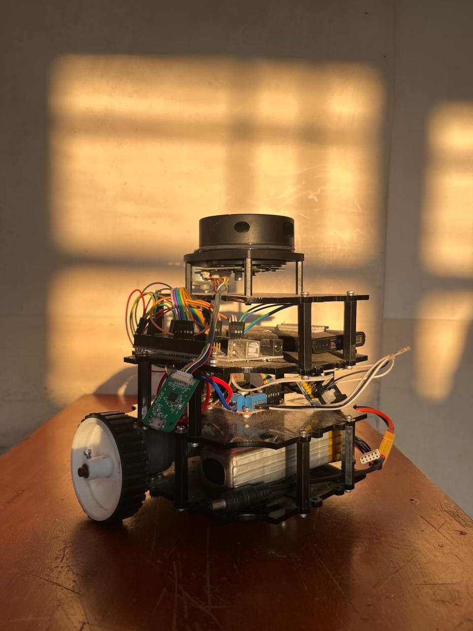
A. Robot Hardware and Middleware Development
Robot Hardware: This stage involves designing and constructing the physical robot platform.
ROS2 Middleware: The Robot Operating System 2 (ROS2) framework communicated between various robot components, sensor integration, and code organization.
B. Agent Code (DRL Algorithm) Development
DRL Base Code: The RL agent's foundational code (basic architecture) was developed. This code would be compatible with various RL algorithms.
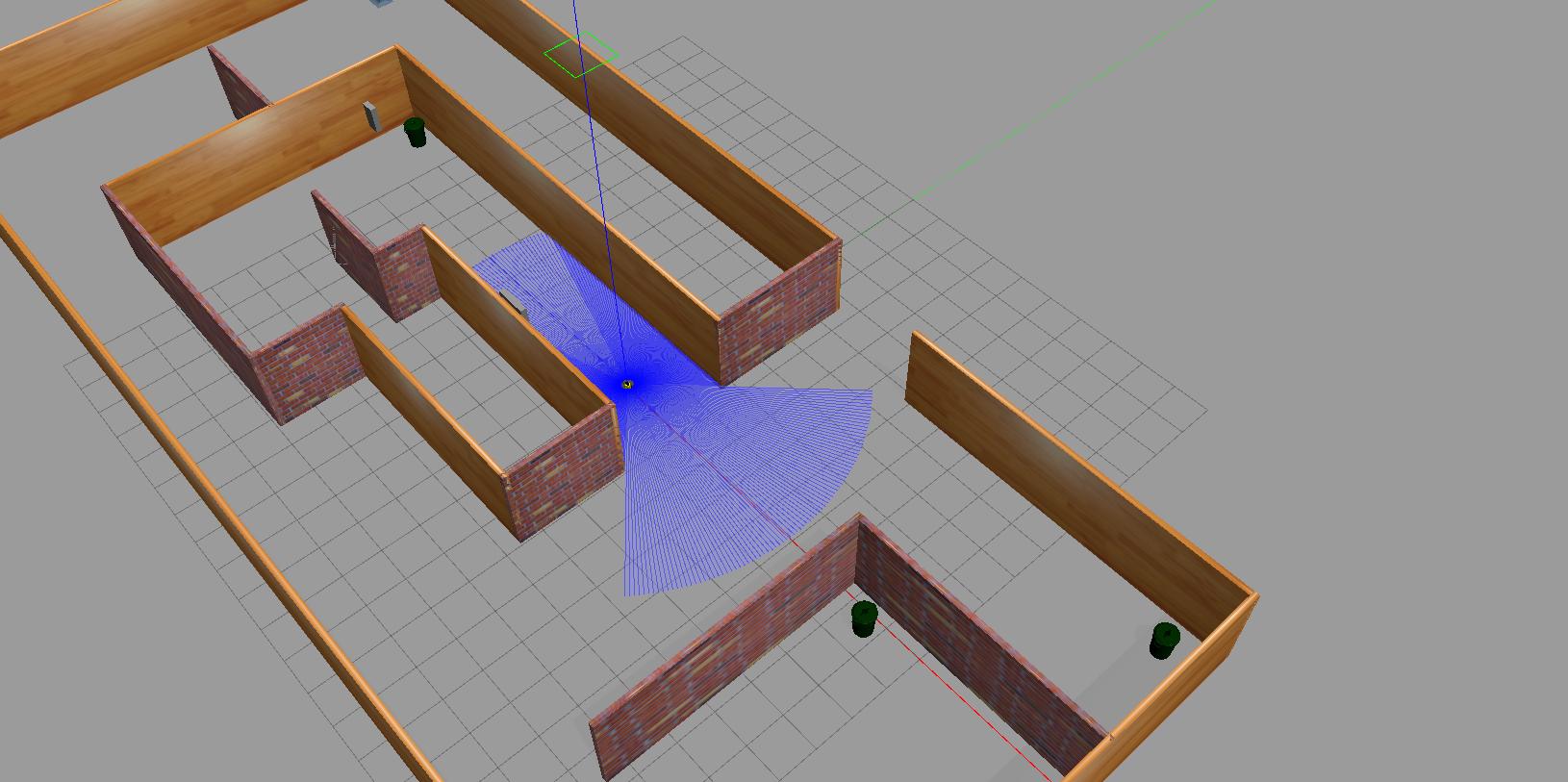
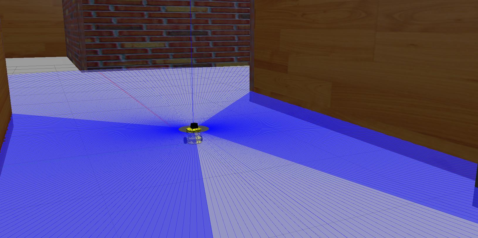
Training Environment: A Gazebo simulation environment replicates real-world RL agent training scenarios.
LiDAR Data Integration: A pipeline was established to stream LiDAR data from the Gazebo simulation to the DRL code, allowing the agent to perceive the virtual environment.
RL Agent Training: The RL agent was trained within the Gazebo simulation using the chosen RL algorithm and LiDAR data. The focus was on avoiding collisions and achieving efficient pathfinding during training.
C. Real-world Implementation and Testing
Once the RL agent achieved satisfactory performance in the Gazebo simulation (accuracy in path planning), the system was transferred to the real robot. The trained RL agent code was deployed on the physical robot platform.
Real-world Testing: The robot was tested in real-world environments to evaluate the effectiveness of the trained RL agent for path planning with LiDAR data.
DEEP REINFORCEMENT LEARNING
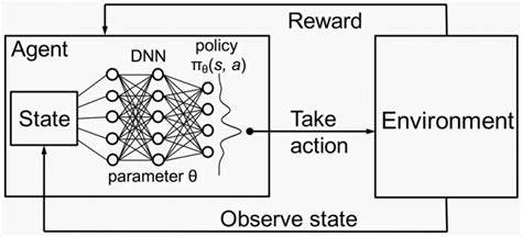
Deep Reinforcement Learning (DRL) is a subfield of machine learning that combines reinforcement learning (RL) and deep learning. RL is a machine learning algorithm that learns to solve a multi-level problem by trial and error. At the same time, DRL incorporates deep learning into the solution, allowing agents to make decisions from unstructured input data without manual engineering of the state space. In this path planning project, Deep Reinforcement Learning (DRL) acts as the brain behind the navigation. The robot interacts with its environment (ROS2, simulation, LiDAR) through actions and receives rewards for getting closer to the goal without collisions. A deep learning model analyzes LiDAR data (robot’s perception) and chooses the best action based on past experiences. This continuous learning allows the robot to adapt to unforeseen obstacles, handle complex environments, and improve its path planning in the real world.
A. Twin Delayed Deep Deterministic Policy Gradient (TD3) Algorithm:
The Twin Delayed Deep Deterministic Policy Gradient (TD3) algorithm is a Deep Reinforcement Learning (DRL) technique designed for continuous control tasks. It addresses a common issue in Deep Deterministic Policy Gradient (DDPG) - overestimating Q-values - leading to suboptimal policy learning. Here’s a detailed breakdown of the TD3 architecture and its core principles:
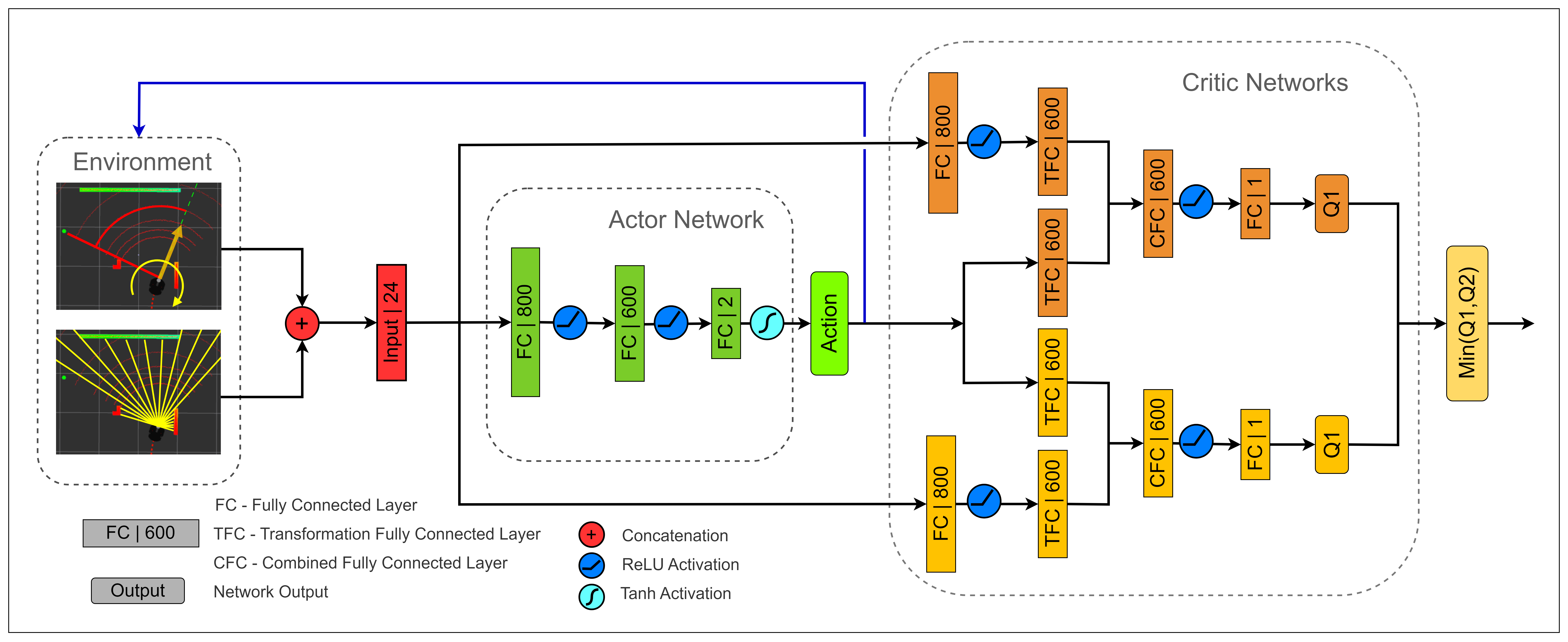
1) Architecture:
1. Deterministic Policy: TD3 utilizes a deterministic policy, denoted as π(s), which always outputs a single ”best” action for a given state s. This deterministic behavior is crucial for tasks like robot control, where consistent and predictable movements are essential.
2. Twin Q-Networks: Unlike DDPG, TD3 employs two separate Q-networks (critics) denoted as Q1 and Q2. These networks independently estimate the expected future reward (Q-value) for a given state-action pair s, a. Having two estimates helps mitigate the overestimation bias that can occur with a single Q-network in DDPG.
3. Target Networks: Two separate target networks, Q′ 1 and Q′ 2 , are introduced as copies of the main Q-networks (Q1 and Q2) but with slower updates. This separation helps stabilize the learning process by providing a stationary target for updating the main Q-networks.
2) Training Process:
Experience Replay Buffer: Transitions s, a, r, s′, done are stored in a replay buffer. These transitions represent the state s, action a taken, reward received r, and next state reached s ′, and a done flag indicating the end of an episode.
Sample Mini-batch: A mini-batch of transitions is randomly sampled from the replay buffer.
1. Target Policy Noise Injection: Noise ϵ is added to the action selected by the current policy π(s) in the sampled transitions. This injects randomness into the exploration process, encouraging the agent to consider a wider range of actions and preventing overfitting.
2. Target Q-value Calculation: The target Q-values (Qtarget) for the sampled transitions are calculated using the target networks (Q′ 1 and Q′ 2 ):
Qtarget(s, a) = min (Q ′ 1 (s ′ , π(s ′ + ϵ)), Q′ 2 (s ′ , π(s ′ + ϵ)))
- π(s): Action selected by the current policy for state s
- min(Q′ 1, Q′ 2 ): Minimum Q-value estimate from the target networks for the next state s ′ and the action selected by the noisy target policy.
3. Q-Network Update: The Q-networks (Q1 and Q2) are updated by minimizing the loss function (mean squared error) between their estimated Q-values (Q(s, a)) and the target Q-values (Qtarget(s, a)) for the sampled transitions:
Loss = E [(Q(s, a) − Qtarget(s, a))2]
4. Delayed Policy Update: The policy is updated less frequently than the Q-networks. This prioritizes learning a stable Q-function before updating the policy. The policy update involves maximizing the expected Q-value from the current state according to the current policy:
5. Target Network Update: The target networks (Q′ 1 and Q′ 2 ) are periodically updated by slowly ”soft” copying the weights from the main Q-networks (Q1 and Q2). This ensures the target networks slowly track the changes in the main Q-networks.
3) Key Improvements over DDPG:
• Reduced Overestimation Bias: Twin Q-networks and target policy noise injection help mitigate the overestimation of Q-values, leading to more stable and data-efficient learning.
• Improved Exploration-Exploitation Trade-off: Noise injection in the target policy encourages exploration, while the deterministic policy focuses on exploitation (selecting the best-known action)
ROS2 AND GAZEBO Simulator
ROS 2 is an open-source framework for robot software development, designed as the next generation of ROS, offering performance, reliability, and scalability improvements. Gazebo, a physics-based simulator for robotics, is commonly used with ROS 2 to simulate robot models, sensors, and environments.
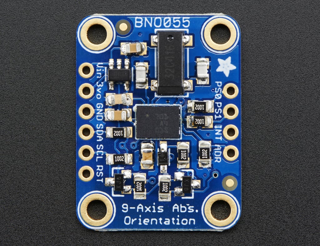
ROS 2 Overview: ROS 2 architecture retains concepts like nodes, topics, messages, and services and introduces new features for enhanced functionality and robustness. Nodes communicate with each other through topics, passing messages containing data. Services enable synchronous communication between nodes, allowing for request-response interactions. The ROS 2 Master facilitates the discovery and communication between nodes in a distributed system. The benefits of ROS 2 include improved real-time capabilities, better support for various platforms, and enhanced security features. Popular ROS 2 libraries and tools include rclcpp (ROS Client Library for C++), rclpy (ROS Client Library for Python), and rviz2 for visualization. The usage of ROS2 in our project can be used both for our simulation in Gazebo and the actual hardware. We can create nodes in ROS2, which can help us communicate between various topics in ROS. For example, for the wheel movement in our robot, we need the data about the position of our robot, which we obtain from the LIDAR. The LIDAR gives the data about the distance of the robot from various obstacles in the surroundings this data is published into the sensor/msg topic. The position and the orientation of the bot are calculated with the help of the IMU(BNO055), and the encoders attached to the motors give data about the position in the x and y axes. This data about the orientation and position of the bot is published into the /Odom topic. The data from the /sensor topic and /Odom topic is taken which is send into the RL model, which gives us the data about the velocity of the bot in the x direction and rotational velocity in the z-axis. In this way, we can simplify the functionality of the bot by using ROS2.
Gazebo Overview: The Gazebo is integrated with ROS 2 to provide a comprehensive simulation environment for robotic systems. It offers a realistic physics engine capable of simulating complex interactions between robots, sensors, and environments. Gazebo’s integration with ROS 2 allows developers to simulate and test ROS 2-based robot systems seamlessly. Its support for various sensors and actuators, along with compatibility with ROS 2, makes it an ideal choice for robotic simulation. Additionally, Gazebo provides tools for visualization, debugging, and analysis, enhancing the development process.
Integration of ROS 2 and Gazebo: ROS 2 and Gazebo collaborate through ROS 2 plugins for Gazebo and ROS 2 nodes controlling simulated robots. ROS 2 plugins extend Gazebo’s functionality, enabling communication with ROS 2 nodes and facilitating the exchange of data. ROS 2 nodes control simulated robots within Gazebo, enabling developers to implement and test robot behaviors in a virtual environment. This integration streamlines the development and testing process, offering advantages such as accelerated prototyping, cost-effectiveness, and improved safety.
The usage of ROS2 in our project: It can be used both for our simulation in Gazebo and the actual hardware. We can create nodes in ROS2, which can help us communicate between various topics in ROS. For example, for the wheel movement in our robot, we need the data about the position of our robot, which we obtain from the LIDAR. The LIDAR gives data about the distance of the robot from various obstacles in the surroundings. This data is published into the sensor/msg topic. The position and the orientation of the bot are calculated with the help of the IMU(BNO055), and the encoders attached to the motors give data about the position on the x and y-axis. This data about the orientation and position of the bot is published into the /Odom topic. The data from the /sensor topic and /Odom topic is taken and sent into the RL model, which gives us the data about the velocity of the bot in the x-direction and rotational velocity in the z-axis. In this way, we can simplify the bot's functionality by using ROS2.
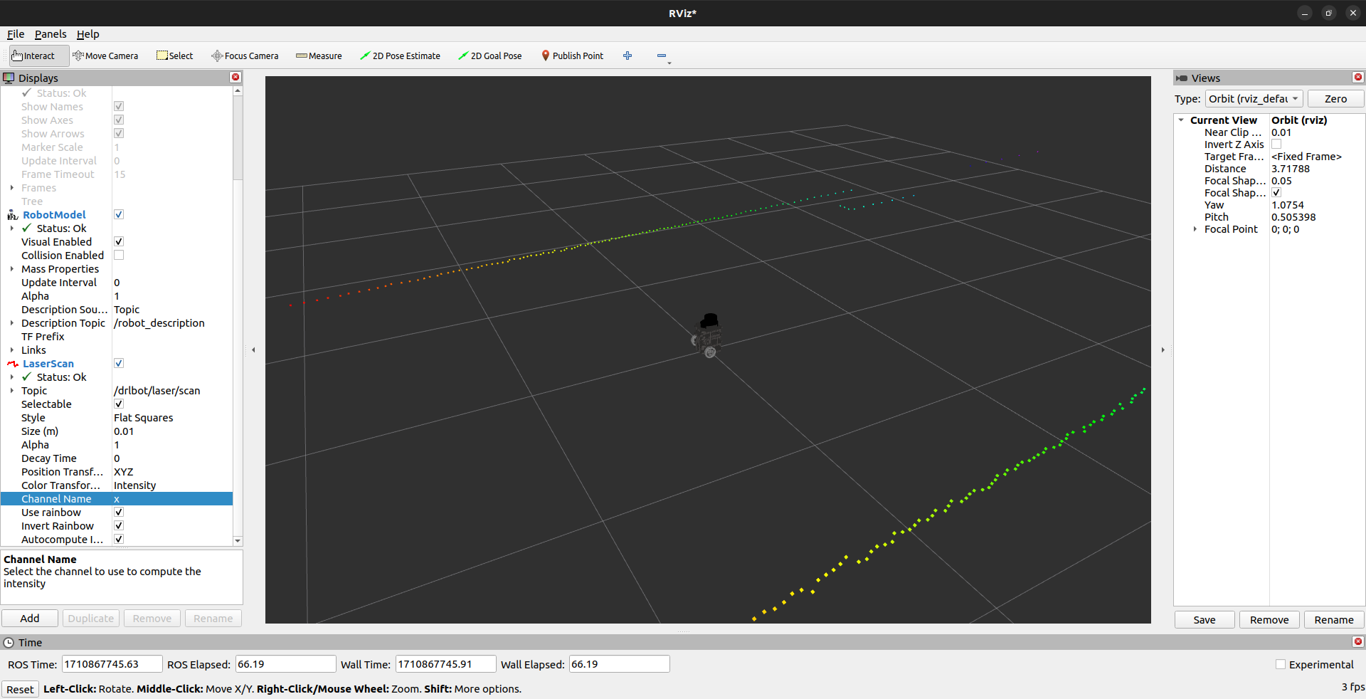
Using Rviz we can check whether the lidar object detection is happening effectively in simulation and the actual hardware of the bot.
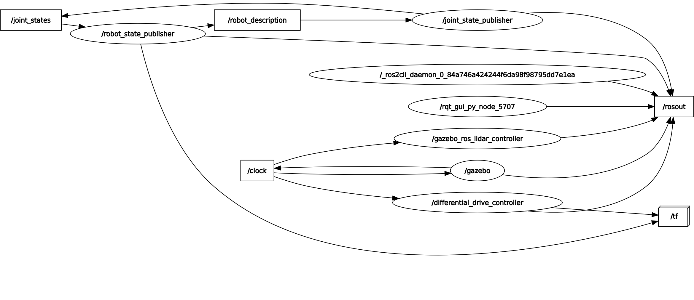
Using the command ”rqt-graph”, we can see the integration between the nodes and the topics in ROS2.
Micro-ROS
Introduction: Micro-ROS represents a significant advancement in the field of robotics by extending the capabilities of ROS 2 to microcontroller-based embedded systems. This report aims to provide an overview of Micro-ROS, its architecture, benefits, applications, and future prospects.
Overview of Micro-ROS: Micro-ROS is an extension of Robot Operating System 2 (ROS 2), which is designed specifically for microcontroller-based embedded systems. It enables the development of ROS 2-based applications on resource-constrained devices, such as microcontrollers, microprocessors, and small single-board computers. Micro-ROS brings the power and flexibility of ROS 2 to the edge, allowing for distributed computing and communication in IoT (Internet of Things) and robotics applications.
Architecture of Micro-ROS: The architecture of Micro-ROS is optimized for resource-constrained environments. It consists of a lightweight ROS 2 client library (rcl) and middleware (rmw) tailored for microcontrollers. Micro-ROS nodes run directly on the microcontroller, communicating with each other. ROS 2 nodes run on more powerful devices over constrained communication channels such as UART, SPI, or CAN bus. Micro-ROS leverages DDS-XRCE (Data Distribution Service for eXtremely Resource Constrained Environments) as its underlying communication protocol, enabling efficient data exchange between nodes.
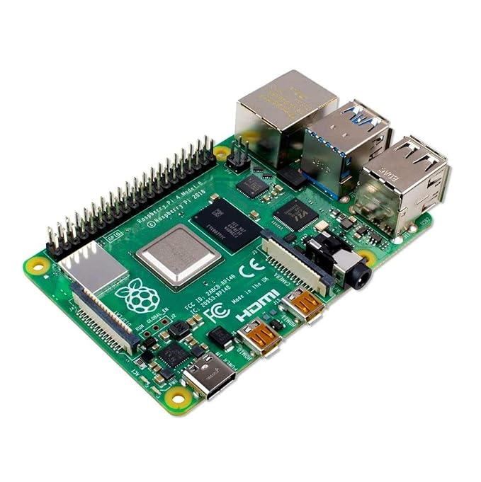
Application of Micro-ROS in our project.: We use Raspberry Pico, which is a micro controller compatible with ROS2. We run micro ros in our microcontroller with the help of Raspberrypi, in which we have loaded ubuntu 22.04, making it capable of running ROS2. By running a micro ros agent in ROS, we can run ROS2 in raspberry-pico through which we can control the various hardware components of the bot
HARDWARE USED
Raspberry Pico H, Rpi 4 model B 4gb, BNO 055 sensor module, Lidar, Motors with attached encoders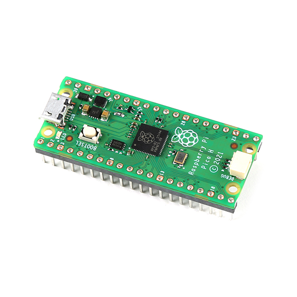

SOFTWARES & PLATFORMS USED
Jupyter Notebook, ROS2 (Humble), Gazebo, Ubuntu 22.04 (Linux) , PyTorch
RESULTS
We developed more efficient navigation of autonomous robots. The robot can learn from past mistakes and aims to perform better.
CONCLUSIONS
This project successfully demonstrated the application of Deep Reinforcement Learning (DRL) in developing an autonomous navigation system for robots. By employing the TD3 algorithm, we achieved a robust navigation strategy that enables goal-driven exploration of unknown environments. Through the integration of ROS (Robot Operating System), our path-planning bot was able to navigate between waypoints and toward specified goals effectively, showcasing its potential for real-world applications. Furthermore, our project contributes to the advancement of autonomous robotics in warehouse environments, offering more efficient and adaptable solutions for inventory management and logistics tasks. By leveraging DRL, our system enables continuous learning and improvement, allowing the robot to adapt its navigation strategy based on past experiences and environmental changes.
REFERENCES
[2] Coursera. Reinforcement Learning Specialization.
[3] Reinis, B. (2022). Creating a Gazebo Simulation with ROS2 for Your Robotics Project.
GITHUB REPO
Path Planning of a Robot using Deep Reinforcement Learning
Report Information
Team Members
Team Members
Report Details
Created: March 21, 2024, 5:33 p.m.
Approved by: Shivani Chanda [Diode]
Approval date: None
Report Details
Created: March 21, 2024, 5:33 p.m.
Approved by: Shivani Chanda [Diode]
Approval date: None