

Autonomous Satellite Collision Avoidance with Inflatable Impact Shield
Abstract
Abstract
The rapid growth of orbital debris in low Earth orbit demands autonomous, low-latency collision protection. This report presents an integrated architecture combining multi-modal sensor fusion, onboard threat assessment, propulsion-based evasive maneuvering, and, as a final passive defense, a deployable Inflatable Impact Shield adapted from crewed habitat technology.
1. Introduction
The increasing density of satellites and orbital debris has significantly raised the risk of high-speed in-orbit collisions, where even small fragments traveling at 7–8 km/s can cause critical damage. This project presents an integrated autonomous collision avoidance framework that combines simulation, predictive algorithms, embedded systems, and structural protection concepts.
Key features:
- Real-time satellite tracking and orbital simulation
- Predictive collision avoidance using PCAM-based logic
- Autonomous trajectory correction through delta-V maneuvers
- ESP32-based hardware warning system
- Simulation of a deployable inflatable boom for passive protection
- Integrated visualization platform for monitoring satellite behavior
2. Simulation of Inflatable Protective Structure
For debris in the 1–10 cm range and MMOD particles that cannot be tracked or avoided, a passive protection system becomes essential. The Inflatable Impact Shield (IIS) adapts multi-layer inflatable habitat technology from NASA TransHab, Bigelow BEAM, and Sierra Space LIFE to provide a lightweight, deployable shielding solution for satellites, offering superior protection compared to traditional rigid structures at significantly lower mass.
The IIS consists of multiple functional layers arranged from outermost to innermost:
- AO/UV protection layer (Beta cloth) to resist atomic oxygen and radiation degradation
- Thermal insulation (MLI) using aluminized Mylar to handle extreme temperature cycles
- MMOD shielding layers (Nextel, Kevlar, foam) that fragment and absorb high-velocity impacts
- Vectran restraint layer providing structural strength and maintaining shape under الضغط
- Redundant gas bladders ensuring continued inflation even after minor punctures
- Inner Nomex/Kevlar liner protecting the satellite from internal damage
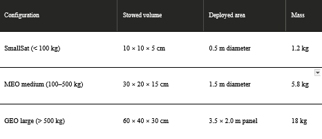
The system is compactly stowed and can be deployed in 10–60 seconds using nitrogen inflation (48–100 kPa), with scalable configurations suitable for different satellite sizes.
Sensor integration with the shield:
The IIS is integrated into the satellite’s autonomy loop for continuous monitoring and adaptive response. MEMS pressure sensors track bladder health, while embedded piezoelectric sensors detect impacts and estimate their energy, enabling real-time damage assessment. Post-deployment, laser rangers verify proper expansion, and the GNC system adjusts for changes in mass and inertia.
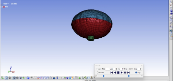
Additionally, a deployable inflatable structure was simulated using LS-DYNA to evaluate inflation and structural behavior. The model included:
- Flexible material definition using MAT_FABRIC
- Inflation modeling via AIRBAG_SIMPLE_PRESSURE_VOLUME
- Contact interactions for realistic expansion
- Boundary conditions representing satellite constraints
The results demonstrate reliable deployment and validate the concept of inflatable structures as effective passive debris shields.
 .
.
3. Satellite Tracking and Visualization GUI
A Python-based graphical interface was developed to simulate satellite motion and monitor potential collision scenarios.
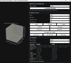
The GUI provides:
• Real-time orbital visualization
• Integration of live satellite data from NASA databases
• Satellite parameter inspection
• Simulation controls
• Interactive visualization (zoom, pan, rotate)
This enables realistic testing of collision avoidance scenarios using real orbital datasets.
4. Satellite Selection and Telemetry Monitoring
The system allows users to select operational satellites such as the Hubble Space Telescope, ISS, and weather satellites to test collision scenarios.
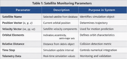
Once selected, the interface displays:
• Orbital parameters
• Velocity and position vectors
• Relative distance measurements
• Live telemetry data
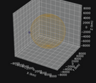
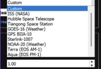
Figure - Orbit Visualization Figure - Satellite Selection
This enables realistic validation of the avoidance algorithm.
5. Collision Detection and Simulation Execution
During simulation execution:
• Satellite and debris trajectories are continuously updated
• Distance calculations are performed in real time
• Close-approach alerts are generated
• Simulation parameters can be modified dynamically
This demonstrates the predictive capability of the developed system.
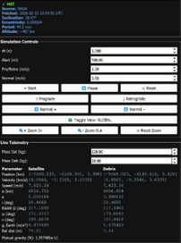
Figure- Telemetry Display
6. Collision Avoidance Algorithm
A Predictive Close Approach Maneuver (PCAM) based collision avoidance algorithm was implemented.
The algorithm performs:
1 Detection of nearby debris
2 Prediction of minimum separation distance
3 Comparison with safety threshold
4 Execution of delta-V avoidance maneuver
5 Trajectory recalculation
Technical features include:
• RK4 numerical integration for motion prediction
• Real-time orbital simulation
• Autonomous maneuver decision logic
• Interactive visualization tools
This enables proactive collision avoidance rather than reactive mitigation.
7. Hardware Demonstration and Warning System Implementation
To validate the practical applicability of the developed collision avoidance framework, a hardware demonstration system was implemented using an ESP32 microcontroller. This subsystem represents a simplified model of how onboard spacecraft computers could process collision warnings and trigger safety responses.
The objective of this hardware implementation was to demonstrate how software-generated collision alerts can be translated into real-time embedded system responses.
Hardware Components Used:
The prototype system consists of:
• ESP32 microcontroller (main controller)
• LED indicator (warning status representation)
• Serial communication interface
• Power supply module
The ESP32 was selected due to its processing capability, GPIO flexibility and suitability for real-time embedded applications.
Working Principle
The hardware system operates based on collision risk data generated by the simulation environment. The simulation continuously evaluates the relative distance between satellite and debris objects. When the distance crosses predefined safety thresholds, warning signals are generated.
These signals are then interpreted by the ESP32 logic to indicate system state through LED behaviour.
The operational workflow is:
- Simulation calculates satellite–debris distance
- Distance compared with warning threshold
- Warning signal generated
- ESP32 receives warning condition
- LED state updated based on risk level
This demonstrates a simplified closed-loop interaction between software prediction systems and embedded response hardware.
Warning Logic Implementation
The warning system is divided into three operational states based on collision probability zones.
- Safe State (Nominal Operation)
When the satellite remains outside the defined warning radius:
• No collision risk is detected
• No avoidance maneuver required
• LED remains continuously ON
• System operates in monitoring mode
This represents nominal spacecraft operation.
- Warning State (Risk Detection)
When the satellite enters the predefined warning zone:
• Collision probability increases
• Avoidance maneuver preparation begins
• LED begins blinking
• System enters alert monitoring mode
The blinking LED represents how spacecraft onboard systems might flag elevated collision risk conditions.
- Post-Avoidance State (Risk Cleared)
Once the avoidance maneuver successfully increases the separation distance:
• Collision risk reduces below threshold
• System returns to safe monitoring state
• LED stops blinking
• Nominal operation resumes
This demonstrates successful execution of avoidance logic.
Embedded System Relevance
This prototype reflects how real spacecraft avionics could implement collision alerts through:
• Flight computer monitoring systems
• Fault detection and warning subsystems
• Autonomous safety triggers
• GNC system alerts
Although simplified, the implementation demonstrates the transition from simulation outputs to hardware-level responses.
Engineering Significance
The hardware demonstration validates three important concepts:
• Software-to-hardware integration feasibility
• Real-time warning logic implementation
• Embedded system applicability in space safety systems
This demonstrates how predictive algorithms developed in simulation environments can be translated into embedded implementations for autonomous spacecraft safety architectures.
8. Conclusion
This project demonstrates a practical implementation of an autonomous satellite collision avoidance framework integrating simulation, algorithm development and embedded hardware demonstration.
Key outcomes include:
• Successful satellite collision simulation
• Implementation of predictive avoidance algorithm
• Hardware warning demonstration
• Simulation of inflatable protective structures
Future work could include:
• Integration with real sensors
• Autonomous GNC implementation
• Machine learning based prediction
• Physical inflatable structure testing
9. Reference
- https://orbitaldebris.jsc.nasa.gov/
- https://ntrs.nasa.gov/api/citations/19910007792/downloads/19910007792.pdf?utm_source=chatgpt.com
Report Information
Report Details
Created: April 8, 2026, 5:17 p.m.
Approved by: Dhruv Kiran Gandhi [Piston]
Approval date: None
Report Details
Created: April 8, 2026, 5:17 p.m.
Approved by: Dhruv Kiran Gandhi [Piston]
Approval date: None