

Optimization of Multi-Element Airfoil Configurations for a Formula Rear Wing
Abstract
Abstract
Mentors: Aryan Lakshmi Subramanian, Ayushman Rastogi, Mohammed Raheesh
Mentees: Jainam Jain, Manas Jagtap, Kshihtij Praveen Narayan
Introduction:
Multi-element wings operate by strategically manipulating airflow through multiple interacting surfaces, allowing for higher effective camber and delayed flow separation. This enables the generation of significantly greater lift coefficients, which translates into improved tire grip and vehicle control. However, designing such configurations is inherently complex due to the large number of interdependent parameters involved. Factors such as element spacing (gap), overlap, chord ratios, angle of attack for each element, and the positioning of the entire assembly relative to the car all interact in non-linear ways. Small changes in one parameter can lead to substantial variations in overall aerodynamic performance, making intuitive design approaches insufficient.
As a result, identifying an optimal configuration requires a systematic and iterative approach. The present study aims to investigate a range of multi-element airfoil configurations through computational analysis, with the primary objective of maximizing the lift-to-drag (L/D) ratio and minimising flow separation. By exploring different geometric arrangements and flow conditions, the study seeks to understand how each parameter influences performance and to identify combinations that yield the best aerodynamic efficiency.
General Procedure:
1. A high lift, low velocity Reynolds number airfoil was chosen for this purpose - Selig S1223 from the airfoil tools site (http://airfoiltools.com/plotter/index?airfoil=s1223- il)
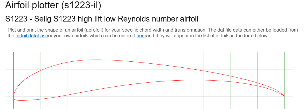
As a sample run, chord was chosen as 100 mm and the CSV file (Excel) of the coordinates was obtained.
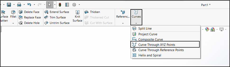
2. The coordinates were then plotted on SolidWorks.
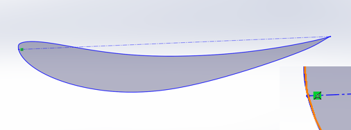
3. After the airfoil curve and was obtained, the main wing was to be setup.
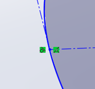
The process began by drawing a construction line from either the leading or trailing edge so that it met the airfoil at the opposite end. From this intersection point, a second construction line was drawn such that it remained tangent to the airfoil surface, helping preserve the smoothness and shape of the curve.
Next, geometric constraints were applied between these lines. In particular, the two construction lines were made perpendicular to each other. This fixed the orientation of the airfoil and removed any unnecessary degrees of freedom, resulting in a fully defined geometry.
For the main wing, the leading edge was fixed at the origin to serve as a reference point. This constraint was not applied to the flaps, allowing them to be positioned relative to the main element as required.
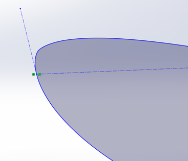
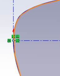
The application of these constraints results in a fully defined airfoil geometry. The horizontal construction line formed during the process serves as the chord line, which becomes the primary reference for aerodynamic analysis. By adjusting the length and inclination of this chord line, the chord length and Angle of Attack (AoA) can be directly controlled.
4. Adding the secondary airfoil element (flap)
The above process was repeated to constrain the flap airfoil. Chord length and AoA were set as per requirement.
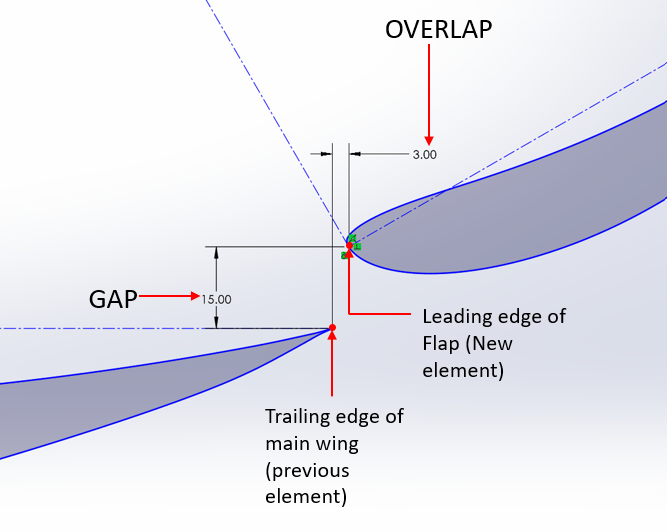
The position of the Flap with respect to the main wing is defined by ‘GAP’ and ‘OVERLAP’. Gap is the distance along y axis, while overlap is the distance along x axis
Once the sketch was completely defined, a planar surface was created using the sketch, and the file was saved in the IGES format for exporting onto Ansys.
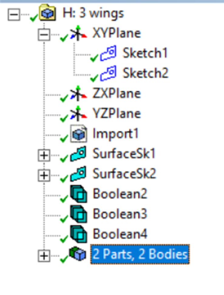
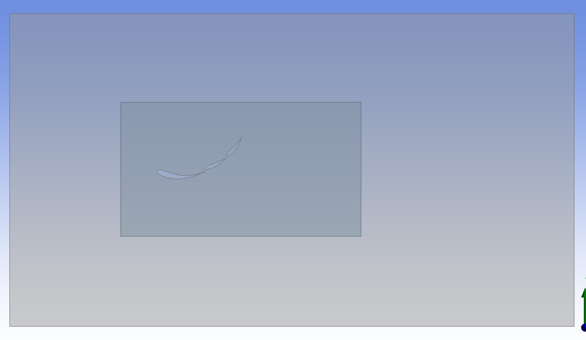
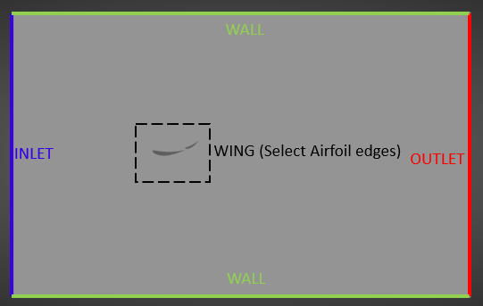
5. On Ansys DesignModeler, a sketch was created for the fluid domain, ensuring that it was sufficiently large to capture the flow field accurately. A second sketch was then developed to define the body of influence (BOI).
Surfaces were subsequently generated from both sketches. For each surface creation step, the “add frozen” option was selected under material settings to maintain independent bodies.
Boolean subtract operations were then performed, using the fluid domain as the target body and the individual wing elements as tool bodies. These operations were carried out separately, allowing greater flexibility in suppressing or modifying specific geometrical features in response to design changes.
At the end of the process, the model consisted of two bodies: one representing the fluid domain with wing-shaped cutouts, and the other representing the body of influence.
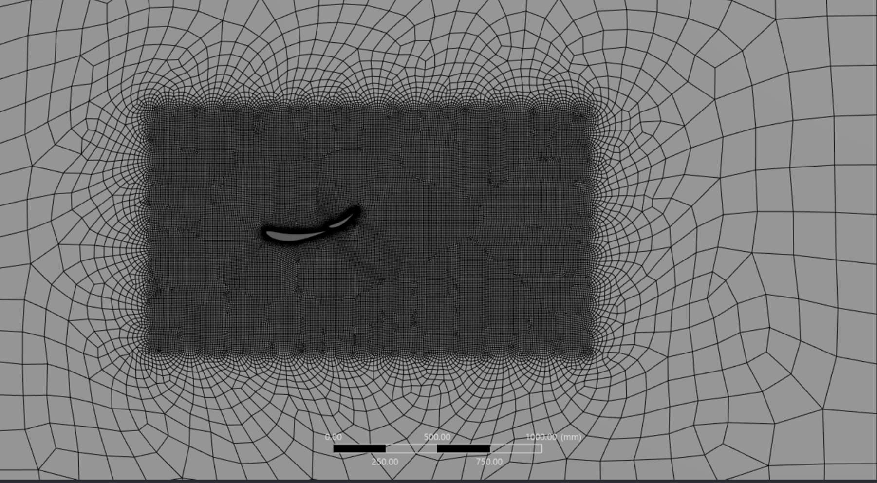
6. Moving onto meshing the geometry,
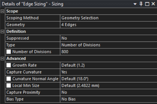
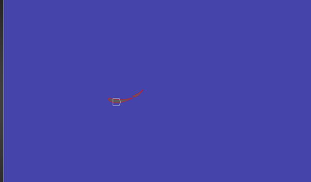
Egde Sizing:
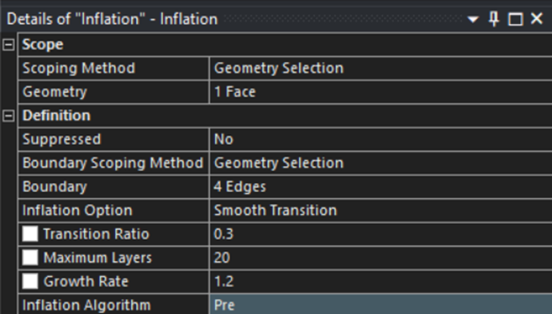
Inflation:
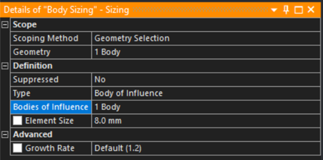
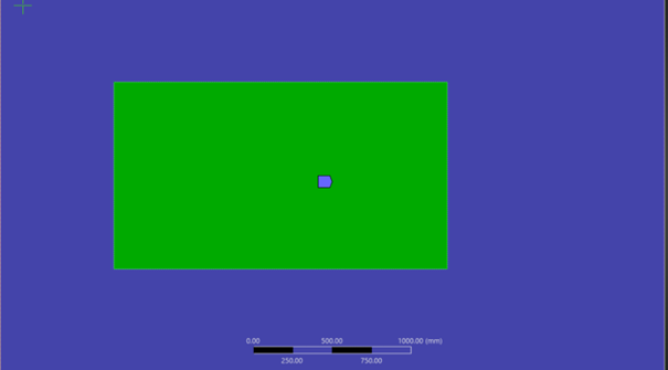
Body of Influence (BOI):
8 mm was chosen because anything below it would severely increase the computational power needed to run the simulation.
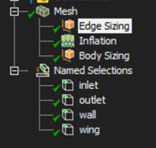
Upon adding the Named Selections,
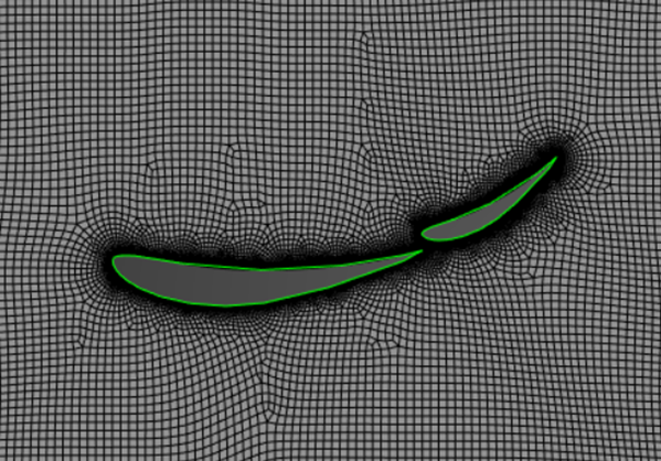
Generated Mesh:
7. Setup conditions:
Steady state pressure based
Viscous SST K Omega model
Inlet velocity = 16m/s (initally), 25m/s for later runs
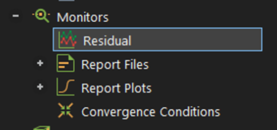
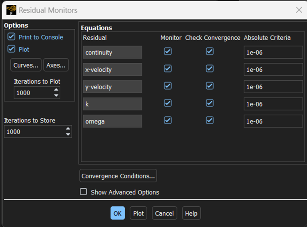
Monitors: residuals-> changed tolerances to 10^-6 from 10^-3 for all residuals
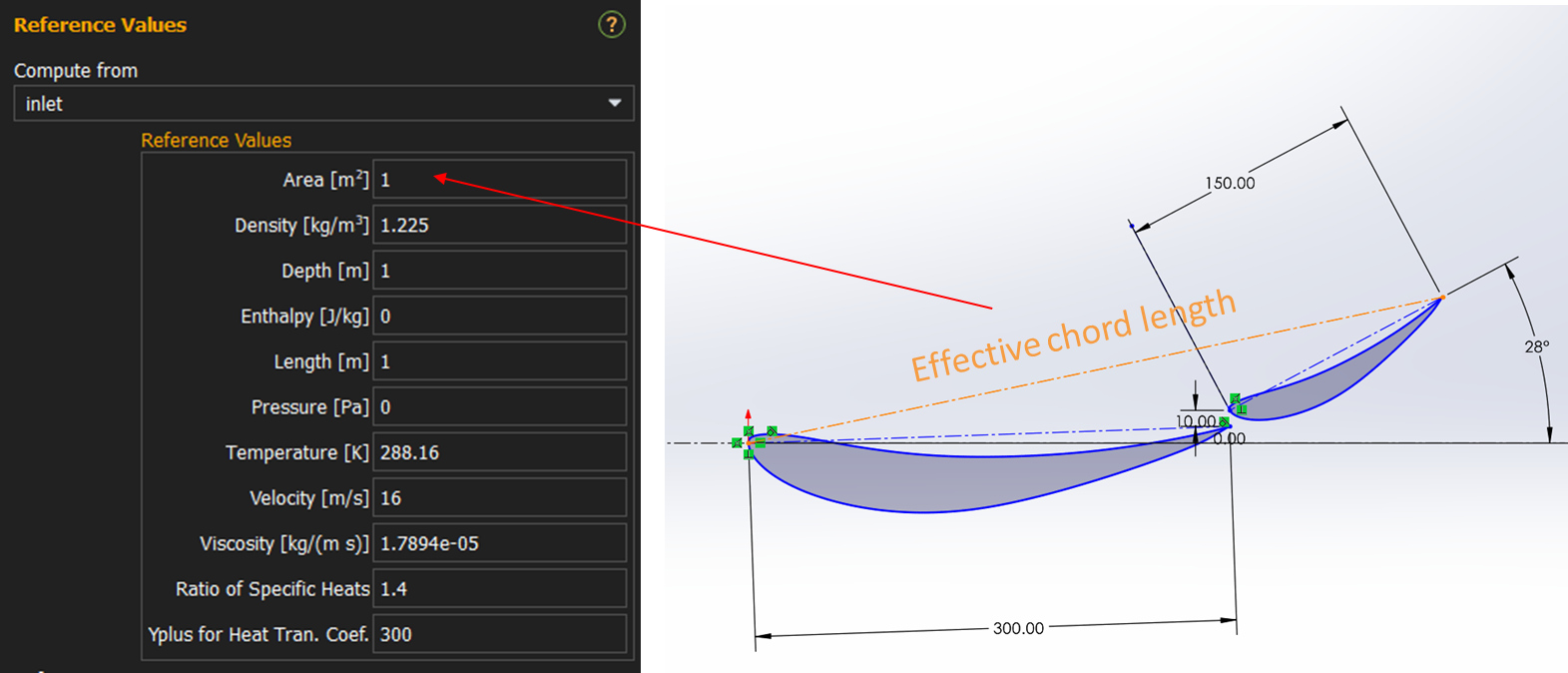
Reference Values: ‘inlet’ in ‘Compute from’ tab
In place of Area, the effective chord length of the Airfoil arrangement was entered
This is important to get Cl Cd values.
Report definitions: Cl, Cd, Lift, Drag on Wing
Initialization: Hybrid
Calculations: 1000 iterations
Methodology and Results:
Upon several trial runs, it was observed that initially AoA had the most impact on the flow conditions through the airfoil. Followed by the chord ratios, and for fine tuning the flow between the elements, the element spacing was adjusted later on.
The range of values to iterate the variables and carry out the corresponding simulations was inspired from the book - Competition Car Aerodynamics 3rd Edition by McBeath, Simon
In the initial runs only two elements were used.
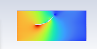
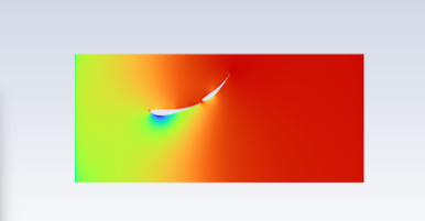
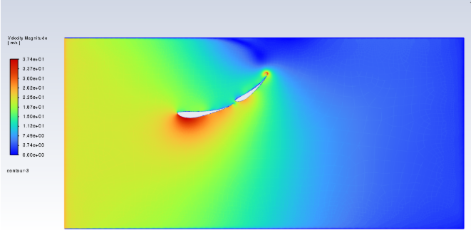
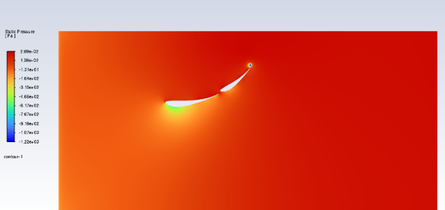
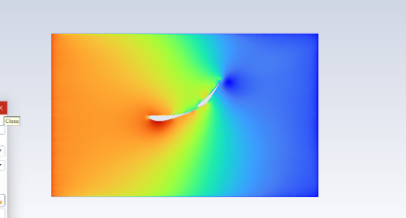
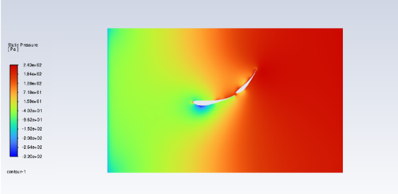
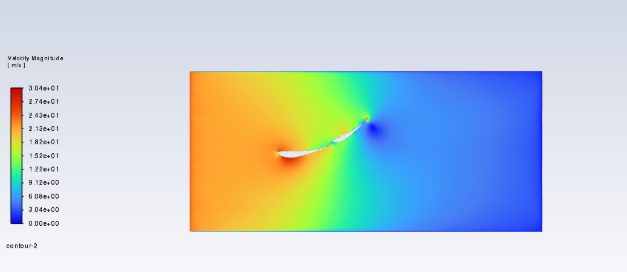
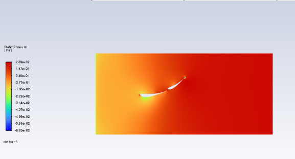
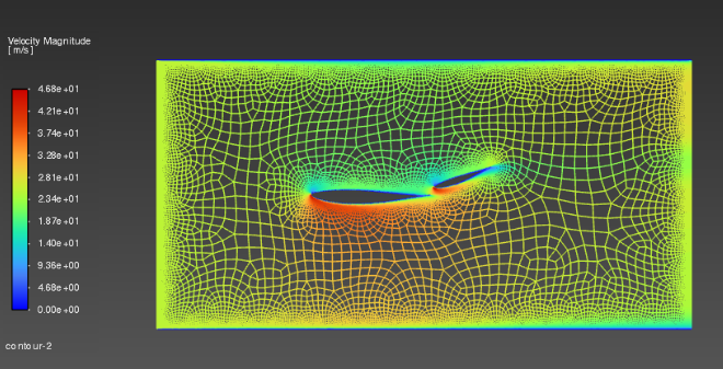
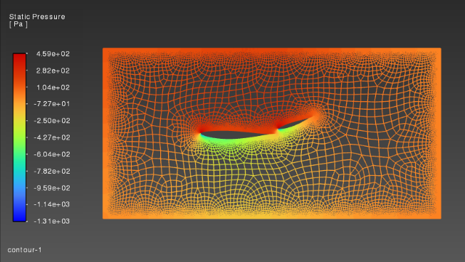
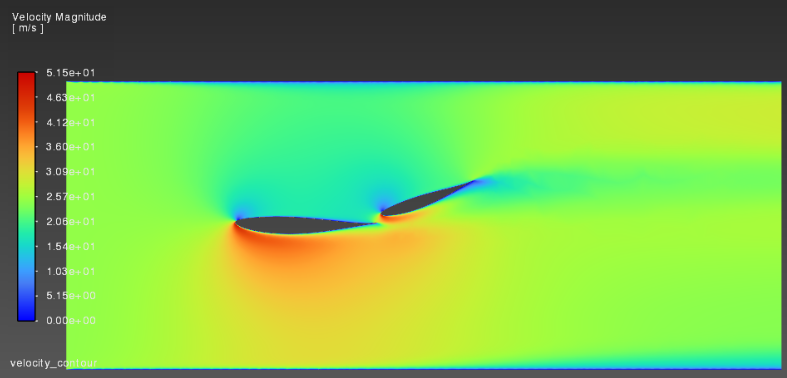
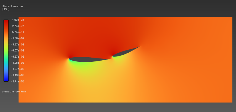
Left - Velocity contours, Right - Pressure countours
AoA (in deg) 10:
L = -0.0119
D = 0.0050
L/D = 2.38
AoA (in deg) 15:
L = -0.039
D = 0.00100
L/D = 39
AoA (in deg) 20:
L = - 0.0225
D = 0.0070
L/D = 3.214
AoA (in deg) 25:
L = -0.0119
D = .0049
L/D = 2.42
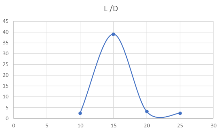
Variation of L/D with AoA:
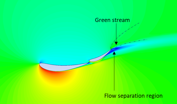
Effect of Chord Ratio:
Chord Ratio-0.5
Chord Ratio - 0.7
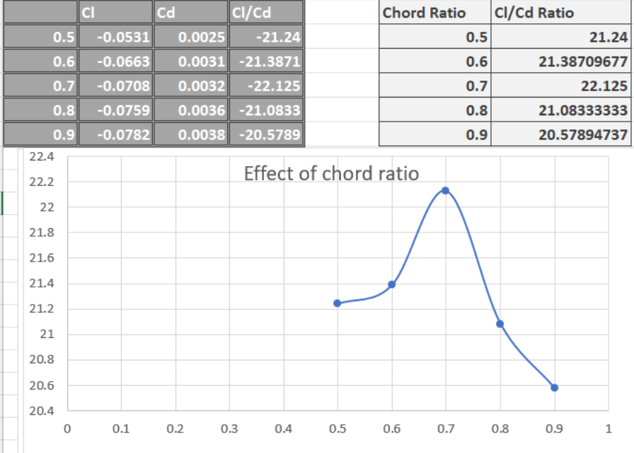
NOTE: the Cl/Cd values appear to be excessively higher than usual because only 2D simulations were performed. Upon running a 3D simulation, the values will be scaled down to a lower value accordingly.
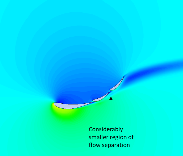
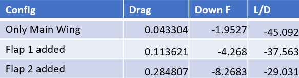
Experimenting with a 3rd element:
References:
Competition Car Aerodynamics 3rd Edition by McBeath, Simon (z-lib.org)
Future possible work:
Carry out 3D simulations.
Implement a DRS model and a mechanism to actuate it.
Report Information
Report Details
Created: April 8, 2026, 5:30 p.m.
Approved by: Dhruv Kiran Gandhi [Piston]
Approval date: None
Report Details
Created: April 8, 2026, 5:30 p.m.
Approved by: Dhruv Kiran Gandhi [Piston]
Approval date: None